


The dreaded GFCI breakers and outlets is something I get asked about often. I actually learned the hard way how they work while I was still apprenticing. I still had a long way to go before writing my ticket and was still a bit green. I knew the gist of what needed to be done to make it work, but I still didn’t understand how a GFCI circuit works and why I was doing what I was doing.
The Circuit
The hard lesson I learned while doing a hot tub install was breaking the neutral. In other words, in a junction box between the panel and the hot tub, I assumed I could cut the neutral and fasten the ends in available terminals in the back of the box. I didn’t know it at the time, but that set forth a chain of events that lead to weeks of multiple electricians troubleshooting something that should have been a very straight forward install and commissioning.
So, a GFCI circuit is designed to constantly monitor and compare the currents on the hot side and neutral side (input and output).
In the fraction of a second that it sees an imbalance, it shuts off all current flow in the circuit.
So, in my disaster, the GFCI breaker was seeing no return current since the terminals I used were grounded to the system (all metal box). An insulated joint in a wire connector would have been sufficient to prevent this mishap, but with two pieces of #6 AWG, the terminals were more appealing.
Repair it yourself
Caveat -always call a qualified electrician to double check your work-
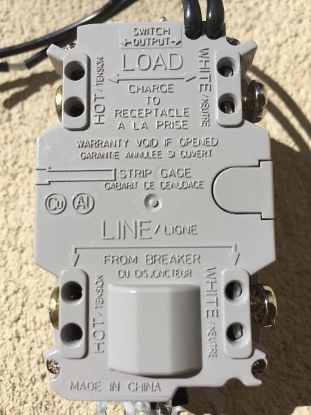
When replacing a GFCI outlet, the most important thing to know is which pair of wires (hot and neutral) in the device box supplies the power. This pair must be installed on the “LINE” side. If this is not identified in anyway, you will need to find this supply voltage with a volt meter. If you do not know how to do this, or feel comfortable doing this, please stop here and call one of us in. Measuring live voltage can be lethal if your fingers are where they should not be. I strongly recommend that wires never be installed in the holes on an outlet, always strip enough copper to make hooks with needle nose pliers and fasten them under the appropriate terminal screws. The black goes under the brass or gold coloured screw. The white under the silver coloured screw. Pro Tip: orient the hook so that it’s looping the screw clockwise so when you snug the screw it adds tension and pulls in the copper in a more secure fashion.
If there is another pair installed on the old GFCI, it is usually feeding power to more outlets downstream. Great news! These outlets are all GFCI protected since they are now connected as a “LOAD” of the GFCI outlet being installed. Install the wires on the LOAD terminals on the receptacles using the same instructions above, and congrats.
You’ve made it through a GFCI replacement.